
Data Center Lux Levels and Server Room Lighting Standards
- Data Center Lux Levels at a Glance
- What Is Illuminance, and Why Does Lux Matter?
- Horizontal and Vertical Illuminance
- Recommended Lux Levels by Data Center Zone
- Rack-Aisle Lighting Layout
- How to Measure Server Room Lux Levels
- Fixture Selection for Data Center Zones
- CAE Three-Level Operational Lighting Framework
- Emergency and Egress Lighting
- Data Center Lighting Standards Explained
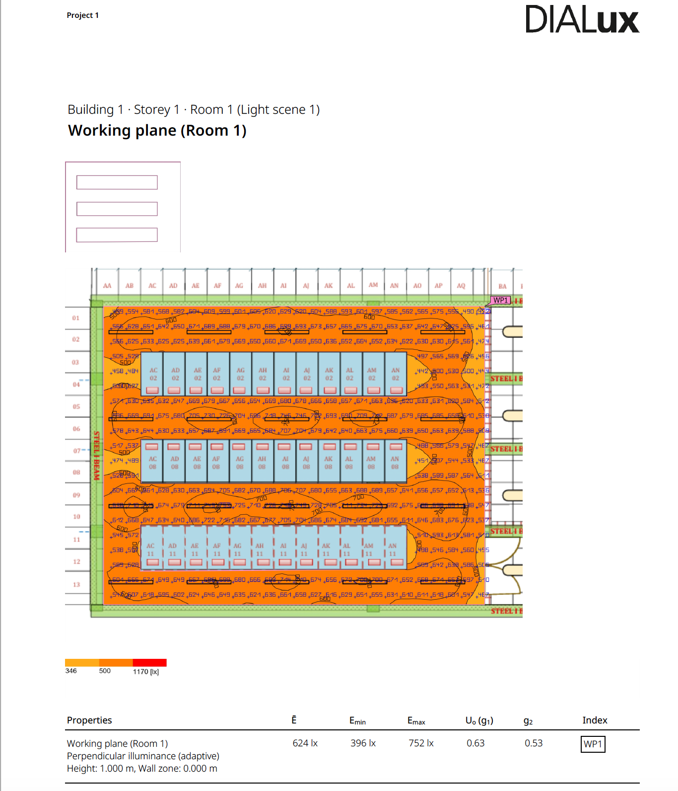
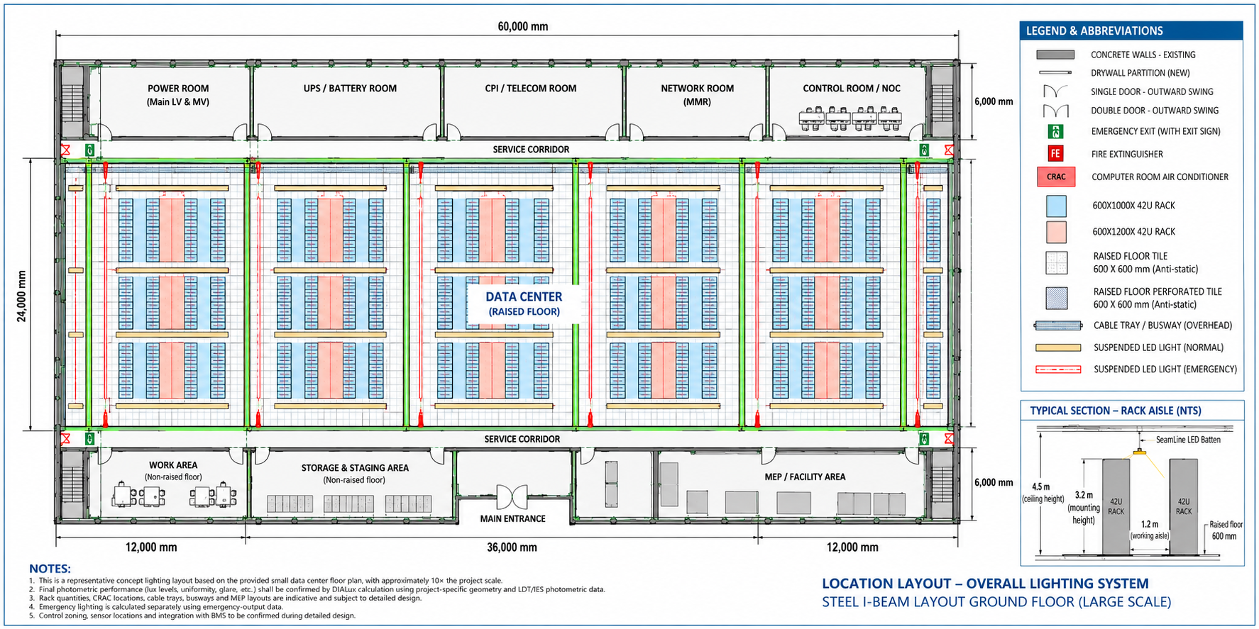
- Representative Data Center Lighting Example
- Common Data Center Lighting Mistakes
- Data Center Lighting Design Checklist
- Frequently Asked Questions
Data center and server room lighting should provide enough light for technicians to move safely, read rack labels, identify ports and complete maintenance without excessive glare or energy use. A practical target for general server and equipment aisles is usually 300–500 lux, measured horizontally at the relevant working plane. Corridors may use approximately 100–200 lux, while NOCs and control rooms commonly require 500–750 lux with controlled glare.
Floor-level lux alone is not sufficient. A complete design must also evaluate vertical illuminance on rack faces, because a floor can appear bright while ports, cable labels and equipment controls remain in shadow. Final values must follow the workplace, energy and emergency-lighting requirements applicable to the project location.
Key Takeaways
- Use 300–500 lux as a practical design range for active server and equipment aisles.
- Measure vertical illuminance on rack faces, not only horizontal lux on the floor.
- Run linear luminaires parallel to rack aisles and position them to avoid cable-tray obstruction.
- Use 4000–5000 K, CRI 80 or higher, and low-glare optics for most technical spaces.
- Specify CRI 90 where accurate cable-color identification is important.
- Use occupancy sensing, zoning and maintenance modes instead of illuminating every area at full output continuously.
- Treat emergency lighting separately from normal maintained illuminance.
- Verify the proposed design with photometric calculations and on-site measurements.
Data Center Lux Levels at a Glance
The following values are practical starting points for design. They are not a universal substitute for local codes, the project specification or a professional lighting calculation.
| Data center area | Practical maintained illuminance | Main design concern |
|---|---|---|
| Server and equipment aisles | 300–500 lux | Rack-face visibility and shadow control |
| Cold aisles | 300–500 lux | Vertical light on equipment fronts |
| Hot aisles | 200–300 lux where tasks permit | Safe access and rear-cabinet maintenance |
| NOC and control rooms | 500–750 lux | Screen glare and visual comfort |
| Electrical and UPS rooms | 300–500 lux | Panel labels and maintenance work |
| Battery rooms | 200–300 lux or project requirement | Chemical environment and emergency access |
| Mechanical rooms | 200–300 lux | Equipment access, moisture and ambient temperature |
| Data connectivity rooms | 300–500 lux | Patch-panel and cable-label visibility |
| Corridors and circulation routes | 100–200 lux | Uniform navigation lighting |
| Detailed maintenance tasks | 500 lux or higher | Small components and cable identification |
| Security and access points | 200–300 lux | Identification and camera image quality |
| Emergency routes | Code-dependent | Initial level, minimum level and duration |
The maintained value is the level expected after allowing for lamp depreciation, dirt and other losses. It should not be confused with the higher illuminance measured immediately after installation.
1. What Is Illuminance, and Why Does Lux Matter?
Illuminance describes the amount of visible light falling on a surface. It is measured in lux, where one lux equals one lumen per square metre.
This sounds simple, but the measurement plane changes the result. A lux meter placed horizontally on a floor or working plane measures horizontal illuminance. The same meter held vertically against the front of a rack measures vertical illuminance. Both are relevant in a data center.
Adequate illuminance supports:
- safe movement through aisles and technical rooms;
- identification of rack numbers, equipment labels and warning signs;
- accurate patching and cable tracing;
- maintenance of UPS, switchgear and cooling equipment;
- CCTV visibility and access-control tasks;
- safe evacuation during a supply failure.
More light is not automatically better. Excessive output can create reflected glare on metal cabinets and screens, increase lighting energy and make bright-to-dark transitions uncomfortable. The design objective is useful, uniform light where people perform tasks.
Lux is not the same as lumens
Lumens describe the total light output of a source. Lux describes how much of that light reaches a surface. A high-lumen fixture can still produce poor rack visibility when it is badly positioned, blocked by cable trays or fitted with an unsuitable beam distribution.
For this reason, fixture selection cannot be based on lumens per watt alone. The designer must also consider mounting height, optical distribution, aisle width, rack height, reflectance, spacing and obstruction.
2. Horizontal and Vertical Illuminance
Horizontal illuminance is often the first value shown in a lighting report. It is useful for checking circulation areas, floors and horizontal work surfaces. In server rooms, however, many critical tasks take place on vertical surfaces.
Technicians look at:
- rack-unit numbering;
- equipment status indicators;
- patch-panel labels;
- circuit identification;
- cable colors;
- handles, latches and warning markings.
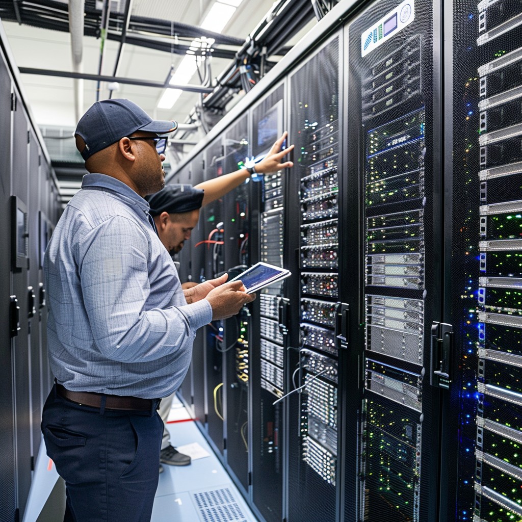
A design that achieves 400 lux on the floor may still leave the lower and upper sections of a rack too dark. Racks, containment panels and cable-management hardware can create deep shadows. Vertical calculation planes should therefore be placed on representative rack faces.
The project should record average illuminance, minimum illuminance and uniformity. A high average can hide very dark points, so average lux alone is not an adequate acceptance criterion.
CRI and cable identification
A color rendering index of CRI 80 or higher is suitable for most data center spaces. Where technicians must distinguish similar cable colors or small color-coded components, CRI 90 can improve identification. Good color rendering should be combined with adequate illuminance; high CRI cannot compensate for a dark rack face.
3. Recommended Lux Levels by Data Center Zone
Different data center spaces support different tasks. One uniform illuminance target across the whole facility usually wastes energy and may still fail to provide enough light in maintenance areas.
Server and equipment aisles: 300–500 lux
For active equipment rooms, 300–500 lux is a practical design range. The appropriate point within that range depends on task duration, label size, equipment density and maintenance procedures.
Aim toward the upper part of the range when:
- maintenance is frequent;
- labels and connectors are small;
- the rack surfaces are dark;
- cable density is high;
- the workforce includes older technicians;
- portable task lights are not part of the operating procedure.
The result should be checked on rack faces, not only on the aisle floor.
Cold aisles: 300–500 lux
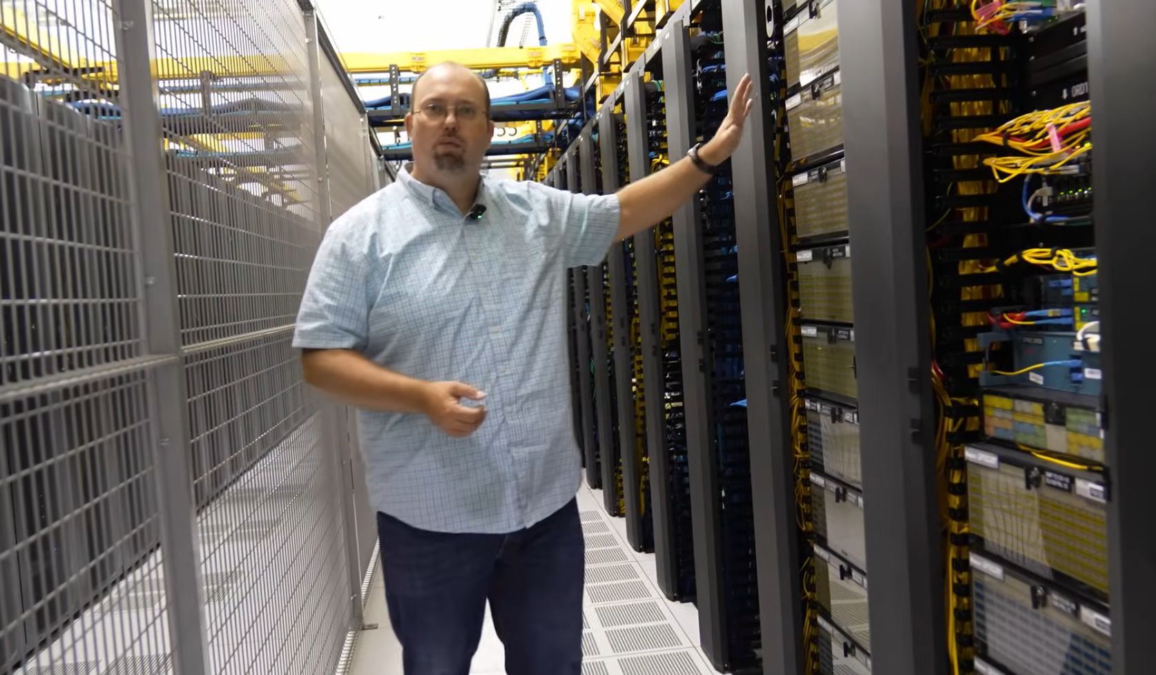
Cold aisles normally face the fronts of the equipment cabinets, where technicians interact with servers and network hardware. Clear vertical illumination is especially important here. Linear fixtures should generally follow the aisle direction and distribute light toward both rack fronts.
Containment ceilings may restrict mounting positions. If luminaires are placed above a transparent or framed containment roof, check losses and shadows created by the structure. Mounting within the contained aisle can improve task visibility, but fixture temperature, access, fire strategy and cabling must be coordinated.

Hot aisles: 200–300 lux where tasks permit
Hot aisles may require less routine access, but they still contain rear connections, power distribution and cable-management points. A lower maintained range can be considered only when it supports the actual tasks and safety plan.
The purpose is not to reduce heat by a trivial change in illuminance. Meaningful energy savings come from zoning, dimming and switching unoccupied areas. During rear-cabinet maintenance, the system should provide sufficient task light through a maintenance mode or local override.
NOC and control rooms: 500–750 lux
Network operations centers combine screen work, communication and document review. The design should balance task visibility with screen comfort.
Use:
- low-glare luminaires;
- UGR below 19 where the applicable design method supports UGR assessment;
- controlled luminance around screens;
- separate dimming zones for display walls and desk areas;
- neutral white light, normally 4000 K;
- good uniformity without excessive brightness on glossy surfaces.
Higher lux is not helpful if poorly shielded fixtures produce reflections on monitors.
Electrical, UPS and power rooms: 300–500 lux
Electrical rooms require clear visibility of panel labels, breaker positions and warning information. Position fixtures so that open cabinet doors and the technician’s body do not block the task light. Emergency illumination and the lighting supply arrangement should be coordinated with the facility’s resilience strategy.
Mechanical and cooling rooms: 200–300 lux
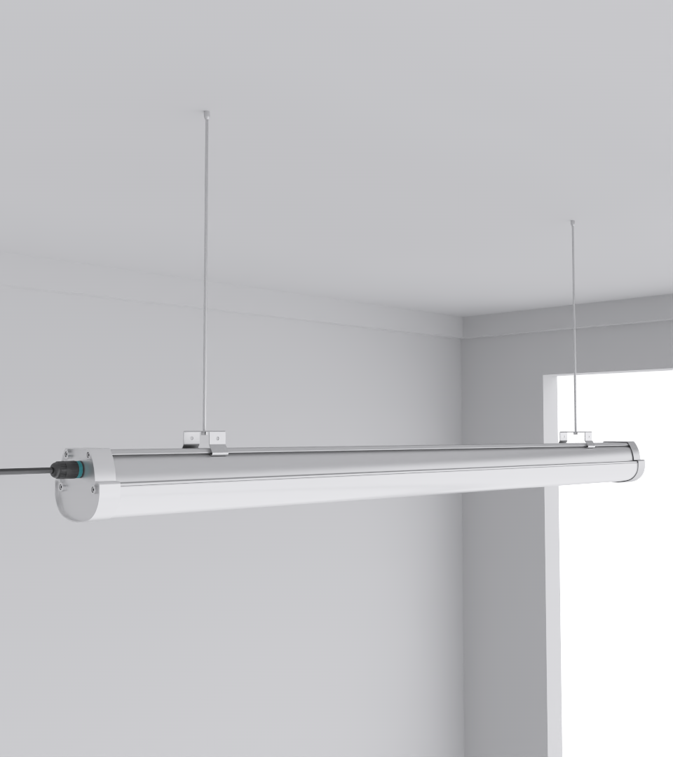
Mechanical rooms need safe access around pumps, valves, CRAC or CRAH equipment and monitoring points. Select the IP rating according to dust and moisture exposure. IP65 or IP66 luminaires may be suitable in wet or exposed areas, but the rating should follow the real environment rather than be specified automatically.
Data connectivity and meet-me rooms: 300–500 lux
These rooms contain patch panels and dense cabling. Vertical illuminance, CRI and shadow control are more important than decorative brightness. Narrow aisles may require continuous linear lighting or closely spaced battens aligned with the cable-management faces.
Corridors and common circulation: 100–200 lux
Corridors need uniform navigation lighting and clear recognition of doors, level changes and signage. Occupancy controls can keep energy use low, but transitions must be gradual enough to avoid sudden darkness around moving personnel.
4. Rack-Aisle Lighting Layout
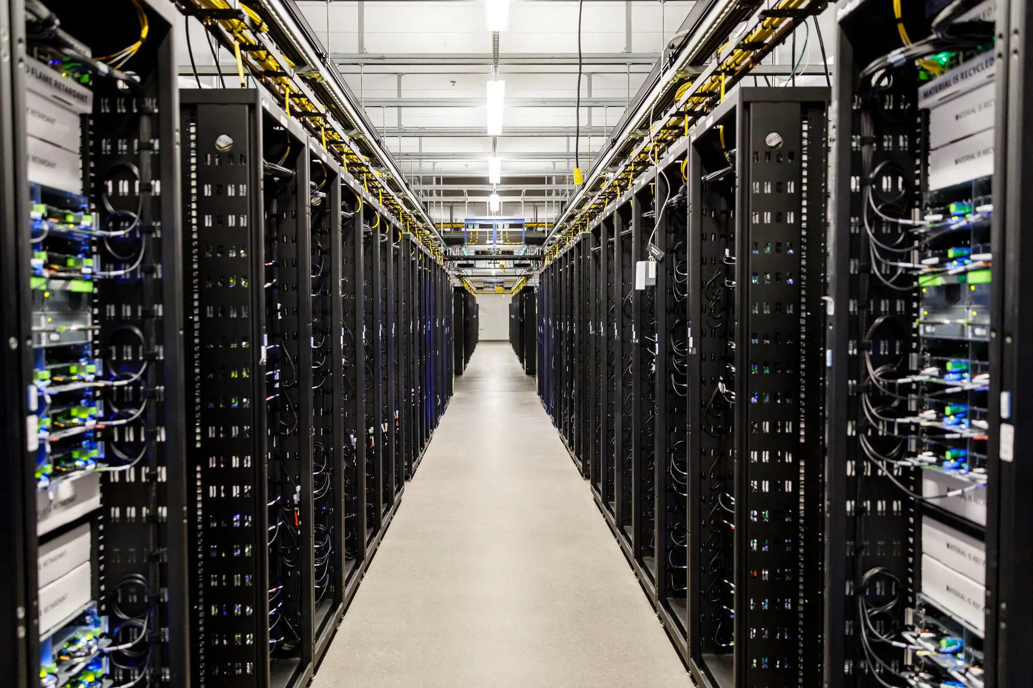
The most reliable starting point is to install linear luminaires parallel to the server rack aisles. This improves continuity, simplifies zoning and helps distribute light along the vertical rack surfaces.
Cable trays and obstruction
An overhead tray installed directly below a luminaire can block much of its useful output. The floor may still receive reflected light while the rack faces become patchy and dark.
Before fixing the lighting layout, overlay:
- rack rows;
- aisle boundaries;
- hot- or cold-aisle containment;
- cable trays and busways;
- sprinkler pipework;
- ductwork;
- access panels;
- security cameras;
- ceiling and suspension points.
If a tray cannot be moved, reposition or suspend the luminaire below it while preserving required clearances.
Mounting height and spacing
Increasing mounting height usually improves uniformity but reduces illuminance at the task plane. Lower mounting can increase useful light on rack faces, but overly wide spacing may create bright and dark bands.
Spacing should be derived from:
- mounting height above the calculation plane;
- fixture photometry;
- aisle width;
- rack height;
- surface reflectance;
- required average and minimum illuminance;
- obstruction from services.
A spacing-to-height rule can support early planning, but it cannot replace a calculation based on the fixture’s actual photometric file.
When suspended lighting is useful
Suspended linear lighting can be effective when the structural ceiling is high or congested. Bringing the luminaire closer to the aisle can improve vertical light and reduce the output needed.
Suspension is particularly useful when:
- ceiling height is much greater than rack height;
- high-level trays block surface-mounted fittings;
- the project needs continuous light lines;
- fixtures must align precisely with aisle centers.
Check vibration, seismic restraint, access, fire services and future rack-layout changes before finalizing the suspension system.
5. How to Measure Server Room Lux Levels
A measurement is useful only when the method is defined. Record the room condition, luminaire state, measurement plane and meter information so future tests can be compared fairly.
Before measuring
Confirm that:
- all relevant normal luminaires are operating;
- dimming is at the intended design level;
- temporary task lights are off unless they are part of the design;
- rack doors and containment panels are in their normal positions;
- the space has reached normal operating conditions;
- the lux meter is suitable and calibrated according to the project procedure.
Horizontal measurement
Create an evenly spaced grid across the aisle or room. Hold the detector horizontally at the specified working plane without shading it with your body. Record each point, not just the highest reading.
Calculate:
- average illuminance;
- minimum illuminance;
- minimum-to-average uniformity;
- any required maximum or diversity ratio.
Vertical rack-face measurement
Hold the sensor vertically and parallel to the rack face. Take measurements at representative heights, including low, middle and high positions. Repeat on both sides of the aisle when the optical layout is not symmetrical.
Measurements near glossy surfaces should be interpreted carefully. Reflections can affect perceived brightness even when the meter reading appears adequate.
Maintenance and retesting
Record a baseline after commissioning. Repeat measurements after major rack-layout changes, lighting-control alterations or luminaire replacement. Periodic readings can identify dirt accumulation, failed drivers, incorrect dimming levels and lumen depreciation.
6. Fixture Selection for Data Center Zones
The luminaire must match the visual task and the environment. Efficacy is important, but optics, glare, reliability and access are equally important.
| Zone | Recommended CAE solution | Selection priority |
|---|---|---|
| Server and rack aisles | SeamLine LED Batten | Continuous distribution and rack-face visibility |
| Humid mechanical areas | AeroLine IP66 | Ingress protection and thermal reliability |
| Tall open technical halls | SquareBeam Elite where photometrics justify high-bay lighting | Mounting height and controlled distribution |
| General high-ceiling utility areas | Budget High Bay | Efficient general illumination |
| NOC and control rooms | Low-glare linear or panel lighting | Screen comfort and uniformity |
| Emergency routes | Approved emergency luminaires or emergency versions | Code compliance and tested duration |
7. CAE Three-Level Operational Lighting Framework
Some facilities benefit from several operating states rather than a simple on/off arrangement. The following is a CAE control framework, not an international standard.
Level 1: Standby orientation mode
Use low-level lighting in selected circulation or security zones during unoccupied periods. Approximately 50–100 lux may be sufficient for orientation where permitted by the project risk assessment. Critical routes and monitored areas may require different settings.
Level 2: Occupied navigation mode
When presence is detected, raise the active zone to a normal navigation level, often around 150–300 lux depending on the space. Adjacent zones can remain at standby rather than switching the whole room to full output.
Level 3: Maintenance mode
Provide the full designed task level, commonly 300–500 lux in equipment aisles and higher where detailed maintenance requires it. Maintenance mode should have a clear manual override and sufficient time delay.
Control safeguards
The controls should prevent unexpected darkness while technicians are working. Include:
- overlapping sensor coverage;
- suitable time delays;
- manual override at accessible locations;
- clear zone identification;
- gradual dimming where practical;
- failure behavior defined in the control sequence;
- separate treatment of emergency luminaires;
- commissioning tests with racks and containment installed.
For a broader controls strategy, coordinate occupancy sensors, DALI or 0–10 V drivers, BMS status points and local operating procedures.
8. Emergency and Egress Lighting
Emergency lighting in data centers is a life-safety system. It must not be designed simply by applying the normal server-room lux target at reduced output.
The project team must determine:
- applicable life-safety and building codes;
- required initial and minimum illuminance;
- measurement plane and uniformity;
- required operating duration, often 90 minutes where the adopted code requires it;
- escape-route and exit-sign coverage;
- independent battery, central battery, generator or UPS arrangement;
- changeover behavior following loss of normal power;
- inspection, functional testing and duration-testing procedures.
Emergency versions of general luminaires can support the strategy when appropriately approved, but dedicated emergency luminaires may still be needed to achieve coverage and compliance.
Lighting controls must not switch off required emergency output. Any interface with the BMS or normal occupancy-control system should preserve the emergency function during a failure.
9. Data Center Lighting Standards Explained
There is no single global document that supplies every lux value, fixture requirement and emergency rule for every data center. The project usually draws from several standards and local regulations.
| Reference | Relevant scope |
|---|---|
| ANSI/TIA-942-C | Overall data center physical infrastructure, including architectural, electrical, mechanical, fire-safety, telecommunications and security considerations |
| ANSI/ASHRAE Standard 90.4 | Energy-efficient design of data centers |
| ANSI/ASHRAE/IES Standard 90.1 or local energy code | Energy provisions for applicable building areas and systems |
| EN 12464-1 or applicable workplace-lighting standard | Indoor workplace illuminance and visual-comfort criteria |
| NFPA 101 or adopted local life-safety code | Emergency egress and life-safety lighting |
| ISO/IEC 22237 series | Data center facilities and infrastructure framework |
| IEC 60598 series | Luminaire safety and construction requirements |
Apply the adopted local requirements
Standards editions, legal adoption and authority requirements vary by country. The final specification should identify the applicable edition, local code and approval authority. Avoid generic claims that one standard guarantees global compliance.
10. Representative Data Center Lighting Example
The following example demonstrates the design process. It is not a substitute for a project-specific DIALux or equivalent calculation.
Project assumptions
| Parameter | Representative value |
|---|---|
| Rack height | 2.0 m |
| Clear aisle width | 1.2 m |
| Luminaire mounting height | 2.8 m above finished floor |
| Target horizontal illuminance | 400 lux maintained |
| Target vertical rack-face illuminance | 200 lux maintained or project requirement |
| Luminaire type | SeamLine linear LED batten |
| Nominal fixture output | 5,400 lm |
| Fixture power | 36 W |
| Arrangement | One continuous row parallel to the aisle |
| Preliminary spacing | 2.4 m centers |
| Color temperature | 4000 K |
| CRI | 90 |
| Control | Occupancy sensing with maintenance override |
Step 1: Build the model
Model the room dimensions, rack rows, containment, cable trays and surface reflectances. Use the actual photometric file for the selected luminaire. Generic symmetrical light distributions can produce misleading results.
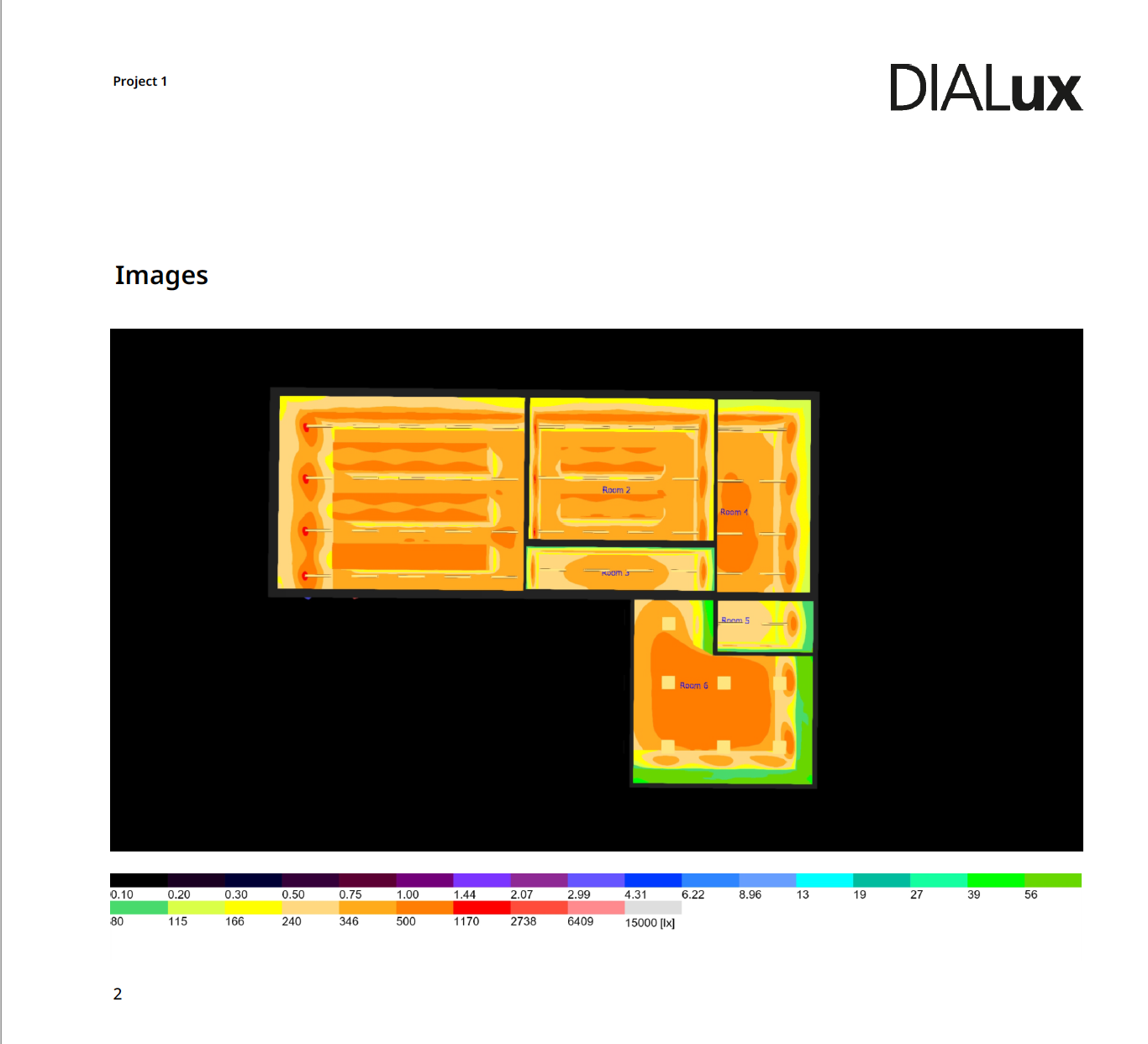
Step 2: Add calculation planes
Create a horizontal grid in the aisle and vertical grids on both rack faces. Add specific calculation points near upper and lower equipment positions.
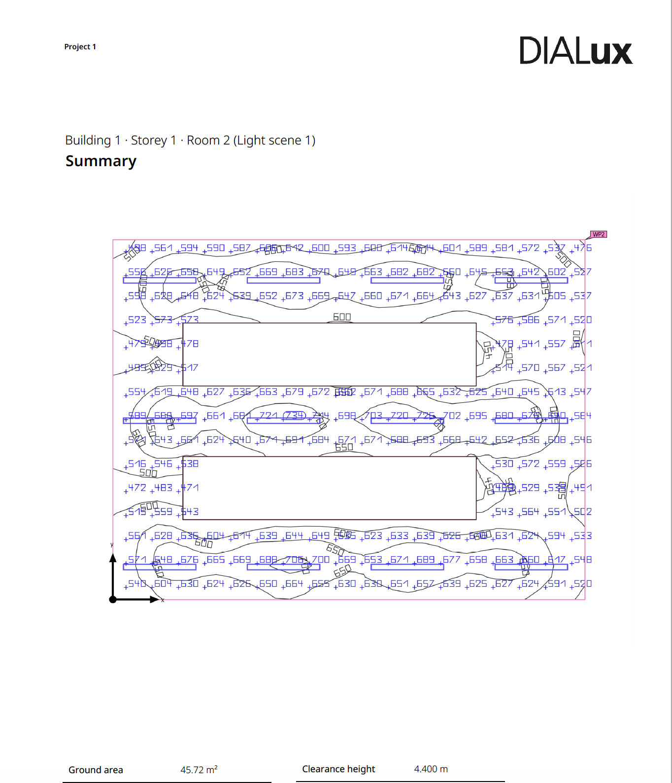
Step 3: Test position and spacing
Place the linear row parallel to the aisle. Check whether the cable tray blocks the distribution. Compare centered, offset and suspended positions before increasing fixture output.
Step 4: Apply maintenance assumptions
Use a documented maintenance factor that reflects the environment, cleaning schedule, LED lumen maintenance and fixture construction. Do not report initial lux as the maintained result.
Step 5: Review more than the average
Confirm:
- average horizontal illuminance;
- minimum horizontal illuminance;
- horizontal uniformity;
- average and minimum vertical illuminance on each rack face;
- glare risk at technician eye level;
- emergency coverage;
- connected lighting load;
- control-zone behavior.
Step 6: Verify after installation
Commission the controls and take field measurements after racks, containment and overhead services are installed. If the rack-face values are low, first check obstruction and positioning before adding more wattage.
11. Common Data Center Lighting Mistakes
Measuring only the floor
This can produce a compliant-looking report while rack labels remain unreadable. Add vertical calculation planes.
Installing luminaires directly above cable trays
The tray can block the most useful part of the beam. Coordinate lighting with overhead services before construction.
Using one illuminance target everywhere
NOCs, corridors, rack aisles and mechanical rooms support different tasks. Use zoning and task-based criteria.
Treating maximum lumens as the goal
Excess output can increase glare and energy use. Select the optical distribution and position before increasing lumen output.
Ignoring containment changes
Adding containment after the lighting design can alter shadows and access. Recalculate when the physical layout changes.
Using short sensor timeouts
Technicians may remain still while working inside a rack. Short timeouts can leave them in darkness. Use overlapping detection, suitable delays and manual override.
Making unsupported standards claims
Do not claim that a general infrastructure standard mandates every lux number in the article. Identify which values are practical recommendations and which are code requirements.
Treating IP rating as complete suitability
IP describes protection against solids and water under specified tests. It does not automatically confirm chemical resistance, hazardous-location approval or high-temperature suitability.
Frequently Asked Questions
What is the recommended lux level for a server room?
A practical target for general server and equipment aisles is usually 300–500 lux. The final value depends on the maintenance task, local requirements and vertical illuminance on rack faces.
Is 300 lux enough for a data center?
It may be sufficient for general movement and routine work when uniformity and rack-face visibility are good. Detailed maintenance, dense patching or small labels may justify a target closer to 500 lux or supplementary task lighting.
Where should lux be measured in a server room?
Measure horizontally on the specified aisle or working plane and vertically on representative rack faces. Record average, minimum and uniformity rather than relying on one spot reading.
Why is vertical illuminance important?
Technicians work on vertical equipment surfaces. Adequate vertical light helps them read labels, identify ports and trace cables even when the floor appears bright.
What color temperature is suitable for data centers?
Most technical areas use 4000–5000 K. NOCs commonly use 4000 K with glare control. Consistency and visual comfort matter more than selecting the highest available CCT.
What CRI should server room lighting use?
Use CRI 80 or higher for general technical areas. CRI 90 is preferable where accurate cable-color identification is important.
Should server-room lights run parallel to rack aisles?
Usually yes. Parallel linear rows provide better continuity and can improve vertical illumination. The final position must account for cable trays, containment and other overhead services.
Can occupancy sensors be used in data centers?
Yes. Use overlapping coverage, appropriate time delays and manual maintenance overrides. Emergency lighting must continue to operate as required independently of normal occupancy control.
Does TIA-942 specify all data center lux levels?
No. TIA-942 is a broad data center infrastructure standard. Lighting design also depends on applicable workplace-lighting, energy and life-safety requirements.
Is 24-hour full-output lighting necessary?
Not normally in every zone. Standby, occupied and maintenance modes can reduce energy use while maintaining safe access, provided the controls are commissioned and cannot leave technicians unexpectedly in darkness.
Plan a Data Center Lux Study with CAE Lighting
For the full fixture-selection and control process, see CAE’s data center lighting design guide. A useful lighting recommendation requires more than room area and wattage. Send CAE Lighting the rack layout, aisle width, rack height, mounting height, cable-tray arrangement and target illuminance. We can prepare a preliminary fixture recommendation, lighting layout and photometric assessment for server aisles, technical rooms and emergency routes.
Include the following with your inquiry:
- floor plan or reflected ceiling plan;
- rack and containment layout;
- mounting restrictions;
- normal and emergency supply information;
- required controls;
- applicable project standards;
- target completion date.
Suggested CTA: Contact CAE Lighting